


 Lighting


Designing a high-performance machine vision system requires more than selecting a camera and turning on a light. In industrial inspection environments, image quality determines measurement accuracy, defect detection reliability, and production efficiency.
This complete 2026 guide explains how to design a machine vision system step-by-step – from selecting industrial cameras to optimizing lighting and optical filters for maximum inspection performance.
What Is a Machine Vision System?
A machine vision system is an integrated combination of hardware and software used to automatically inspect, measure, and analyze products during manufacturing.
Unlike consumer imaging systems, industrial vision systems are designed for:
- High-speed inspection
- Micron-level measurement accuracy
- 24/7 reliability
- Harsh industrial environments
A typical machine vision system includes:
- Industrial camera
- Precision lens
- Controlled lighting
- Optical filters
- Mounting and mechanical accessories
- Vision processing software
Each component directly impacts final image quality and inspection performance.
Core Components of a Machine Vision System
Understanding each component is critical before beginning system design.
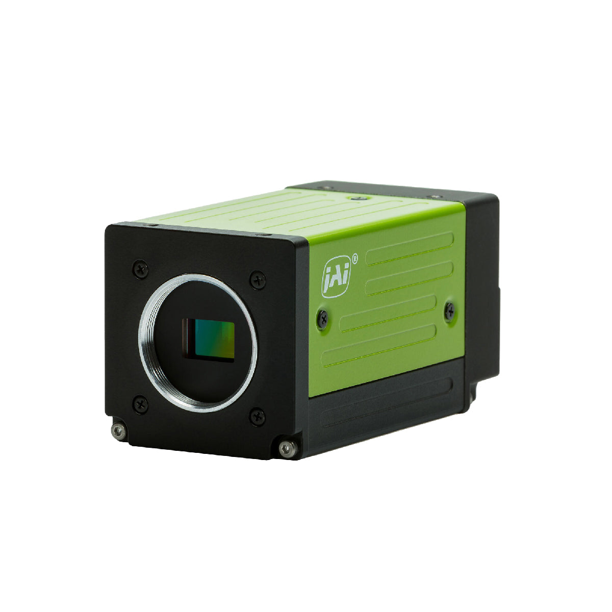
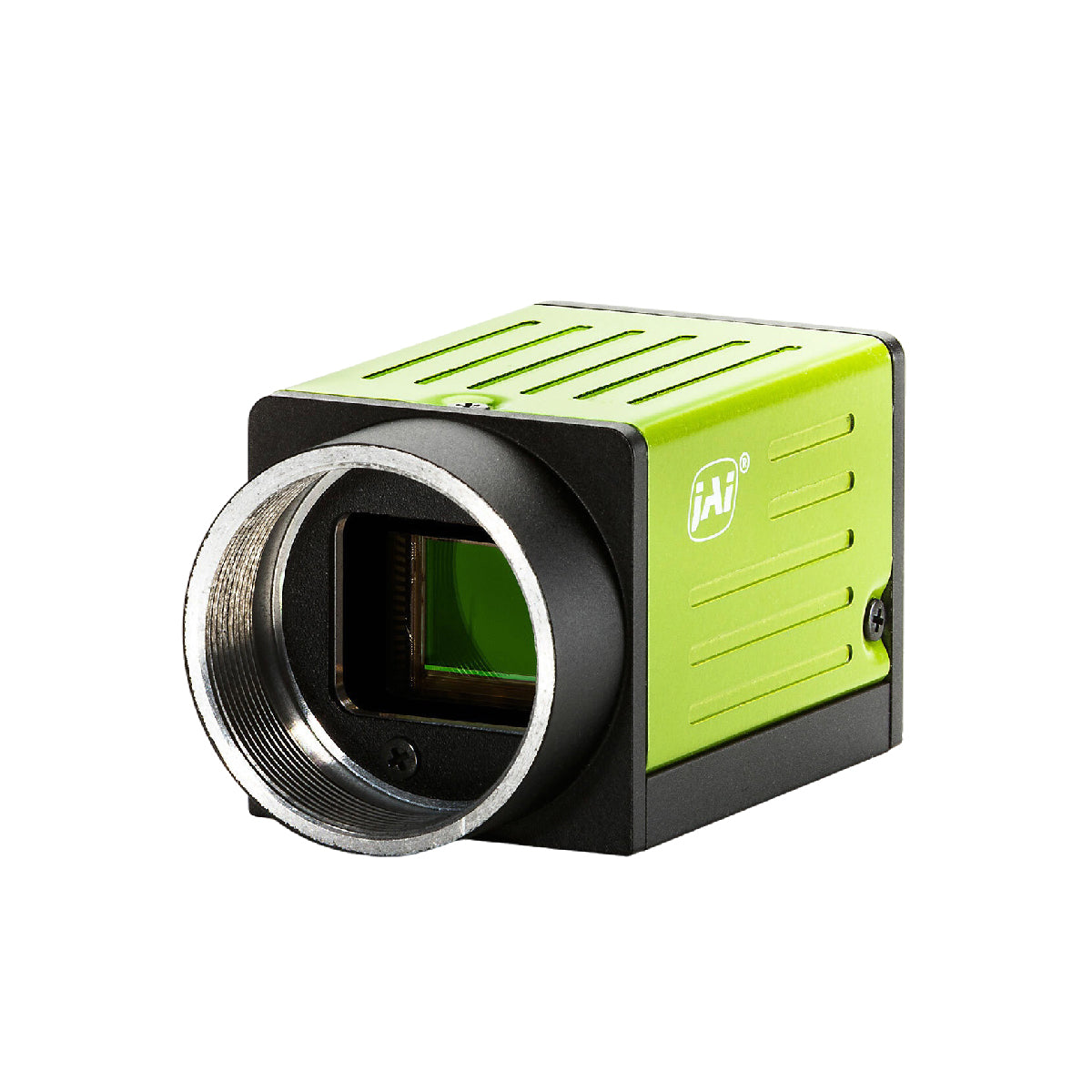
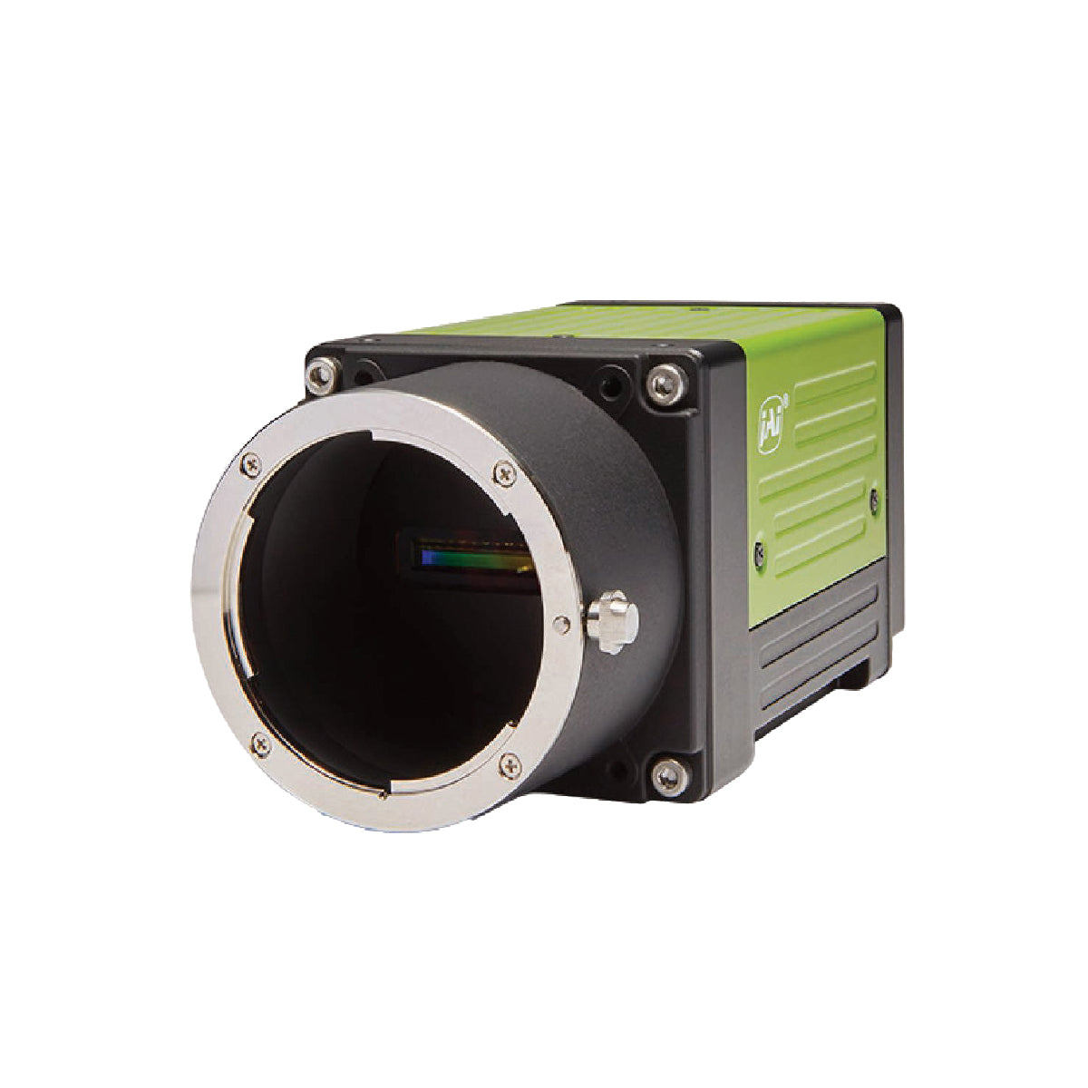
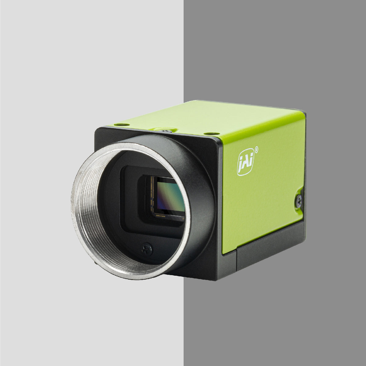
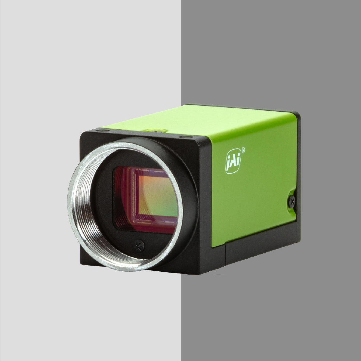
1. Industrial Cameras
The camera is the image acquisition device and the foundation of any vision system.
When selecting industrial machine vision cameras, consider:
Resolution
Higher resolution enables detection of smaller defects but increases processing load.
Frame Rate
High-speed production lines require faster frame rates to avoid motion blur.
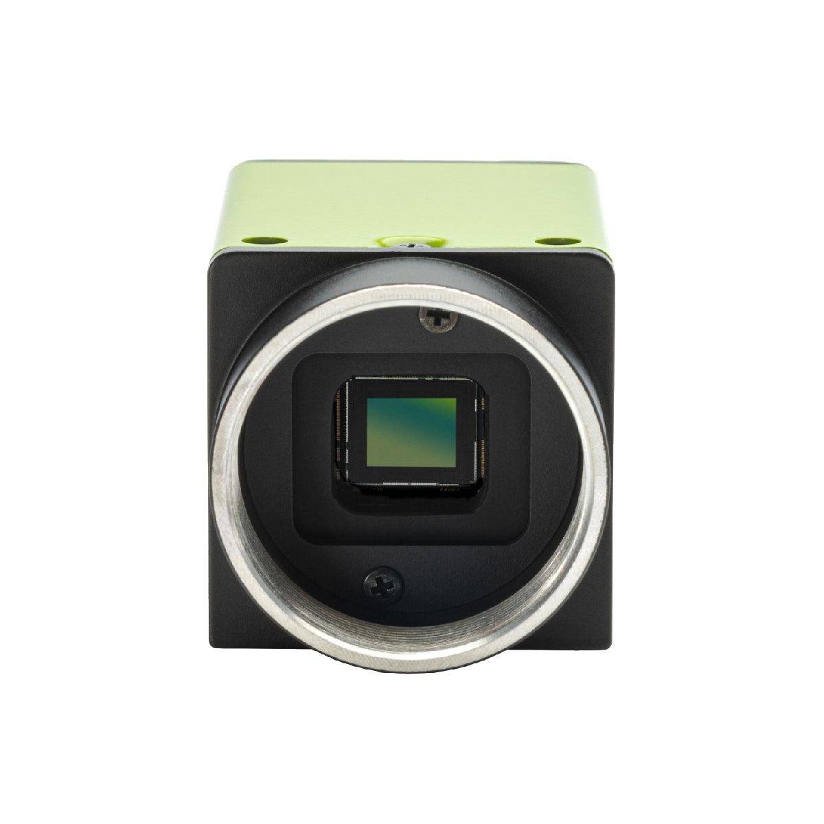
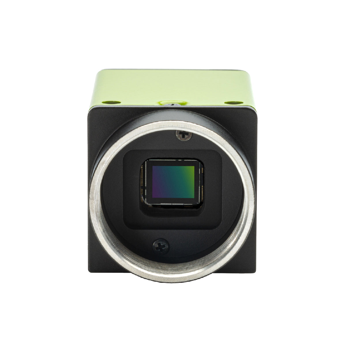
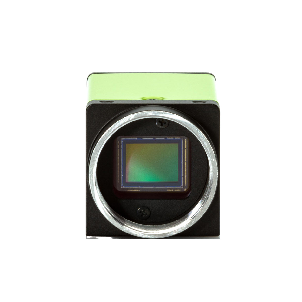
Sensor Type
- CMOS sensors dominate modern industrial applications
- Global shutter preferred for moving objects
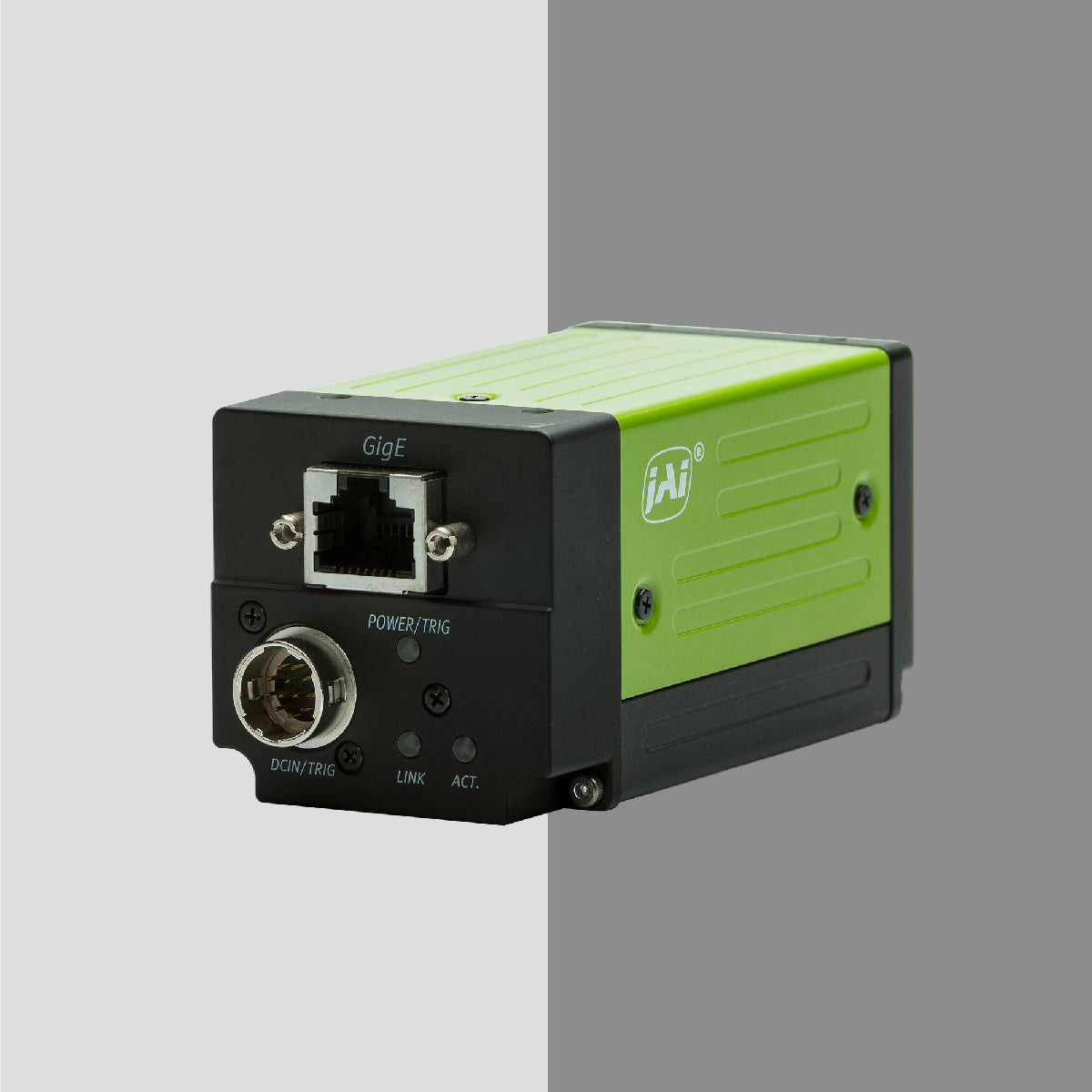
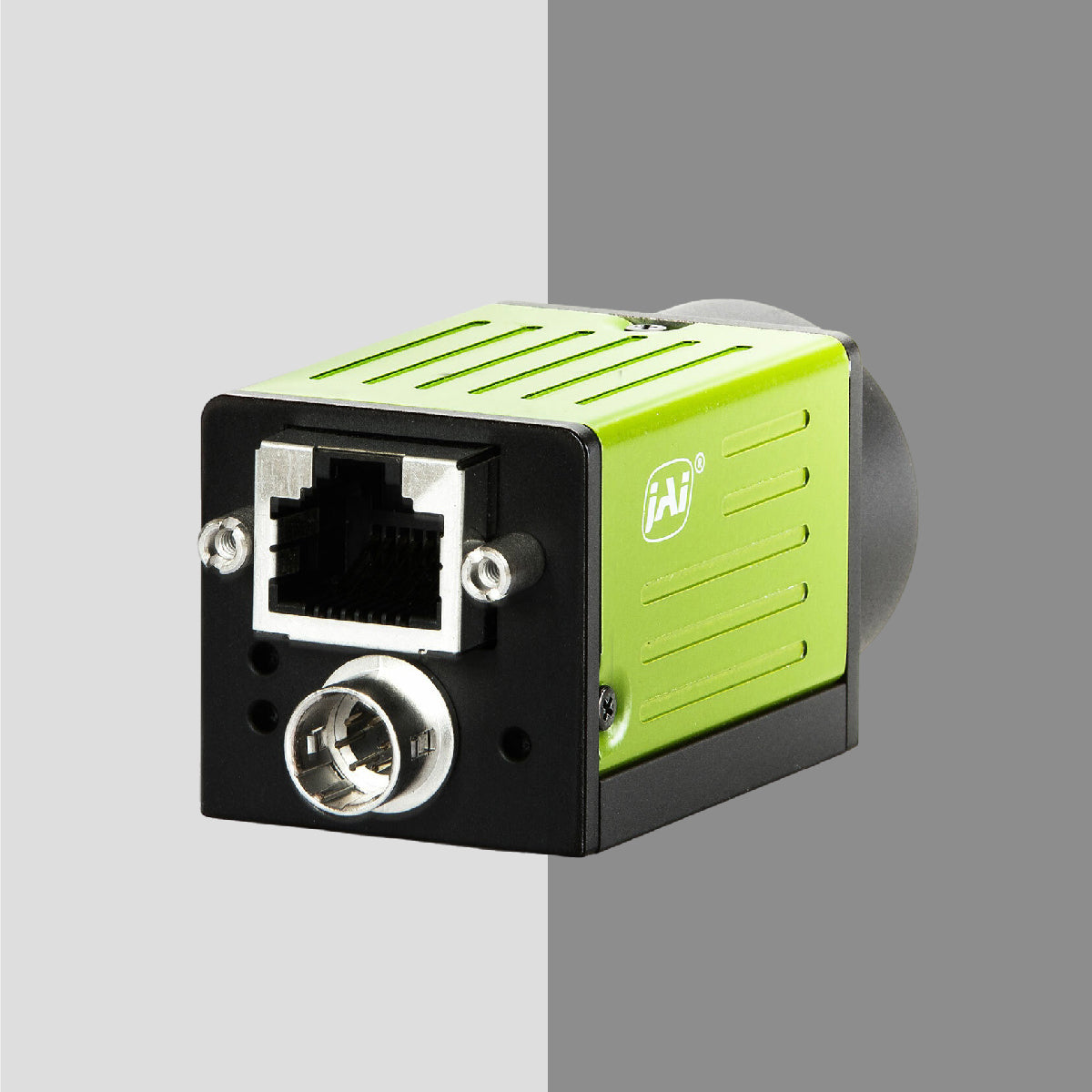
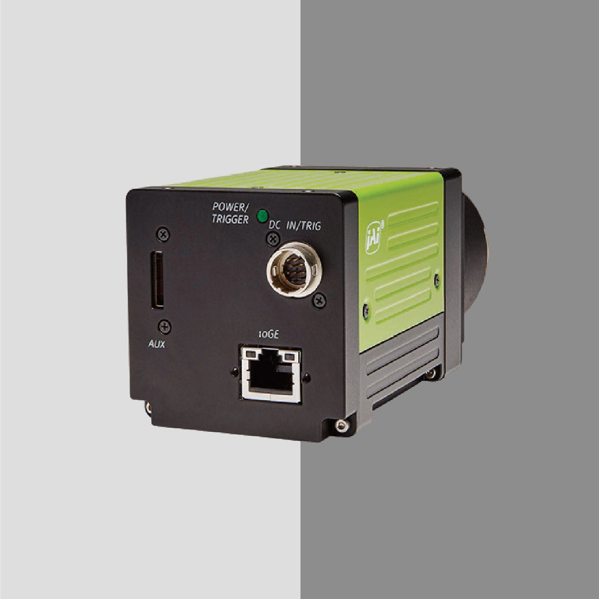
Interface
Common interfaces include:
- USB3 Vision
- GigE Vision
- CoaXPress
- Camera Link
The right industrial camera must match your inspection speed, resolution requirements, and environmental constraints.
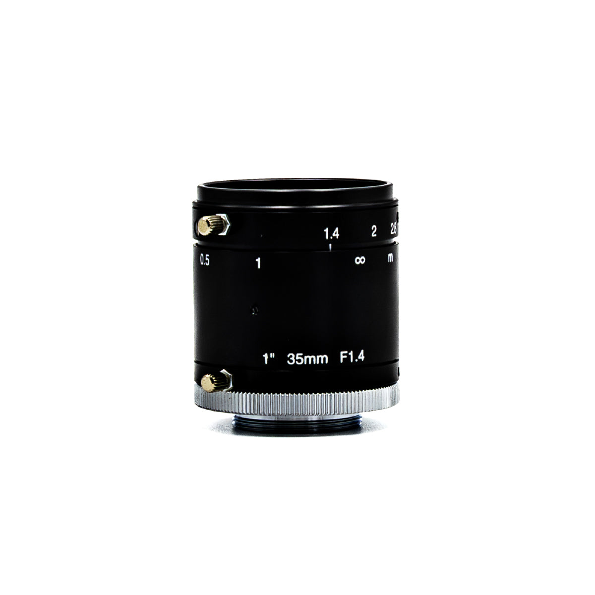
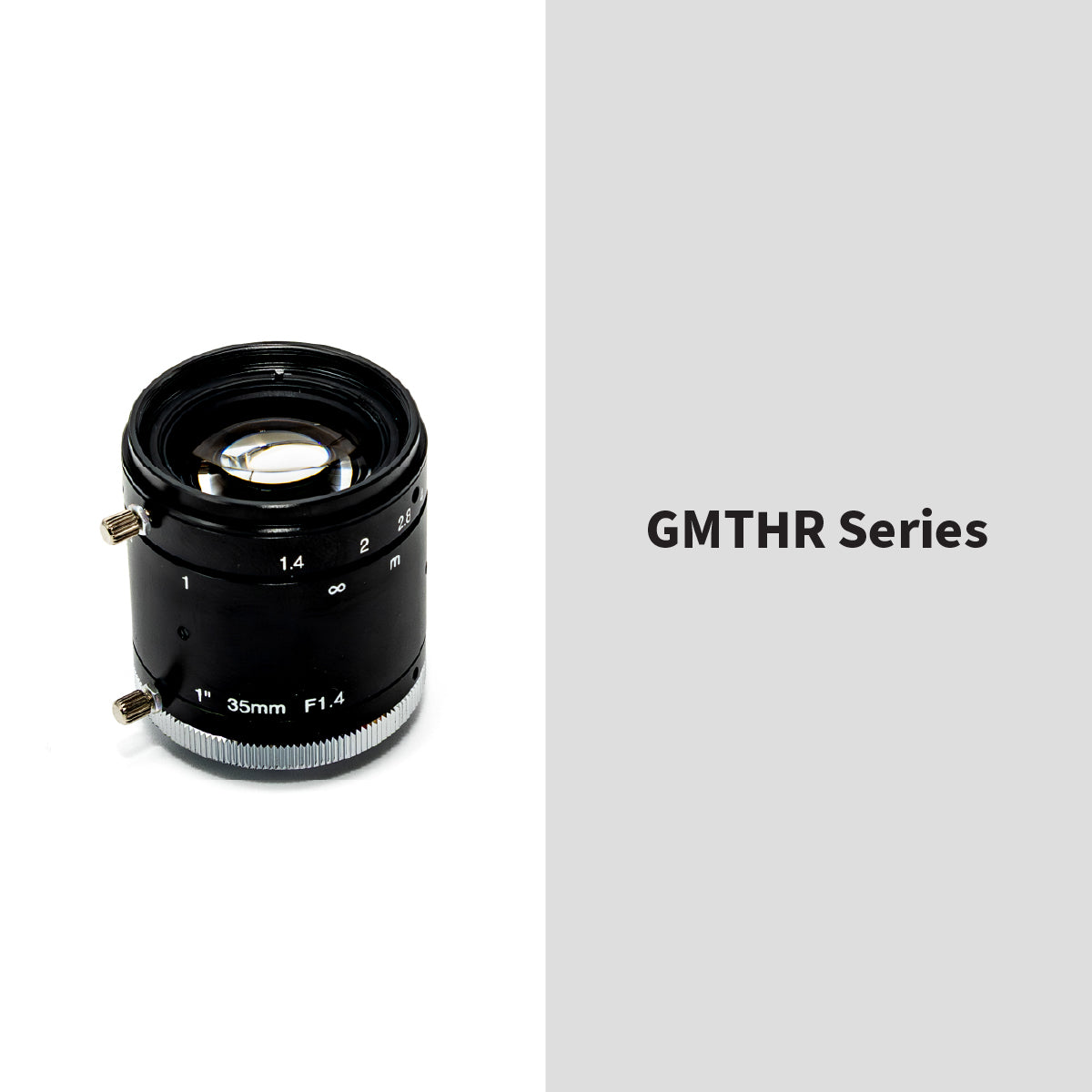
2. Precision Lenses
Even the best camera will fail without the correct lens.
Lenses determine:
- Field of view
- Magnification
- Working distance
- Distortion levels
Key considerations:
Sensor Compatibility
Lens image circle must match sensor size.
Focal Length
Short focal length = wider view
Long focal length = narrow field, higher magnification
Depth of Field
Critical for 3D or uneven surfaces.
Precision optical lenses must be selected based on measurement accuracy requirements — not guesswork.
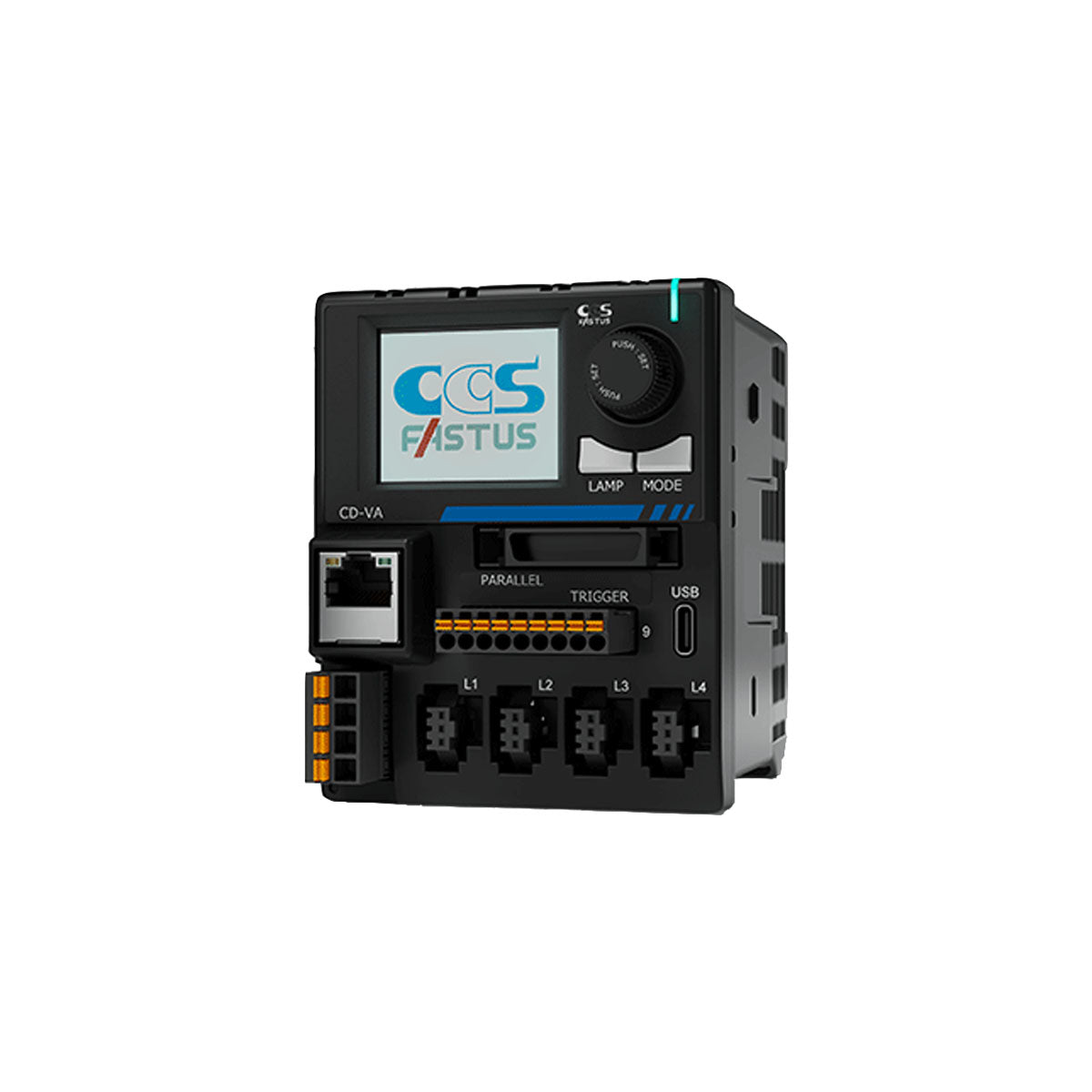
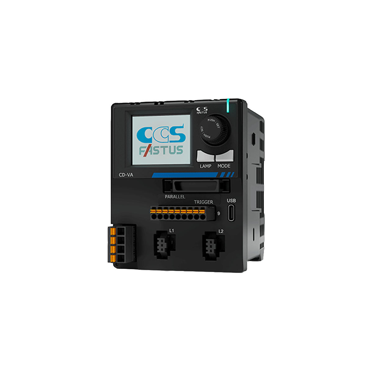
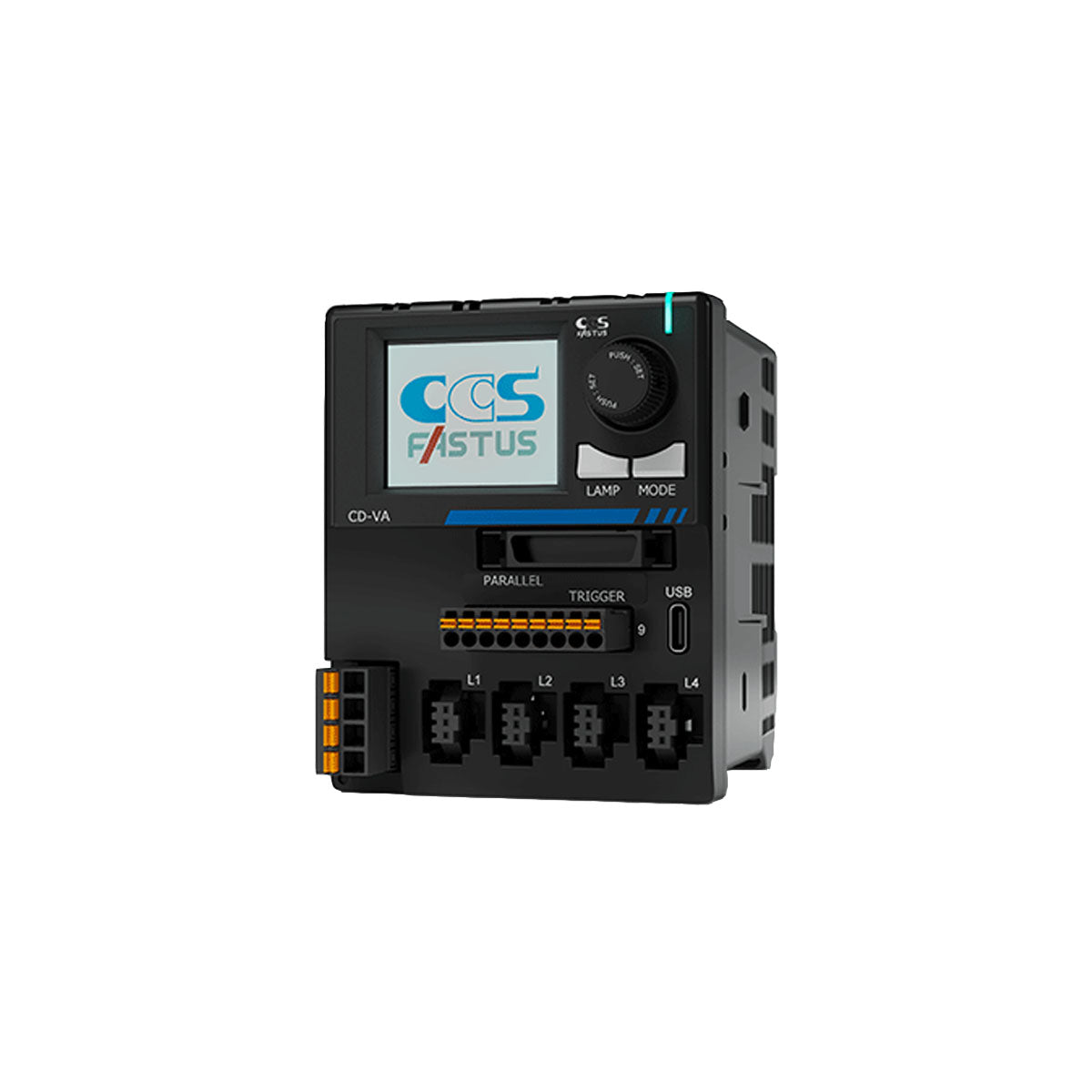
3. Industrial Lighting Systems
Lighting is the most underestimated factor in machine vision system design.
Poor lighting causes:
- Low contrast
- Reflections
- Washed-out images
- False defect detection
Common lighting types:
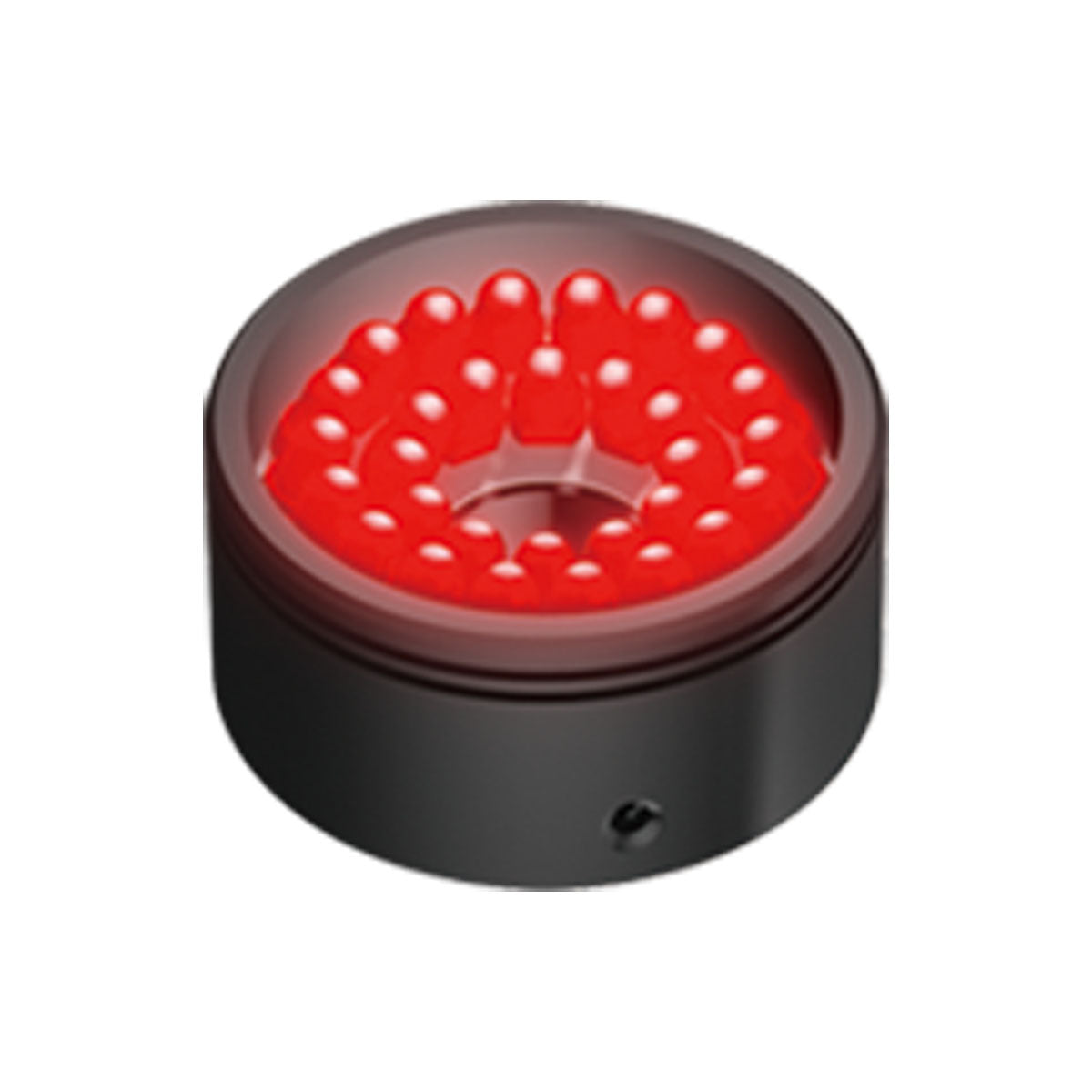
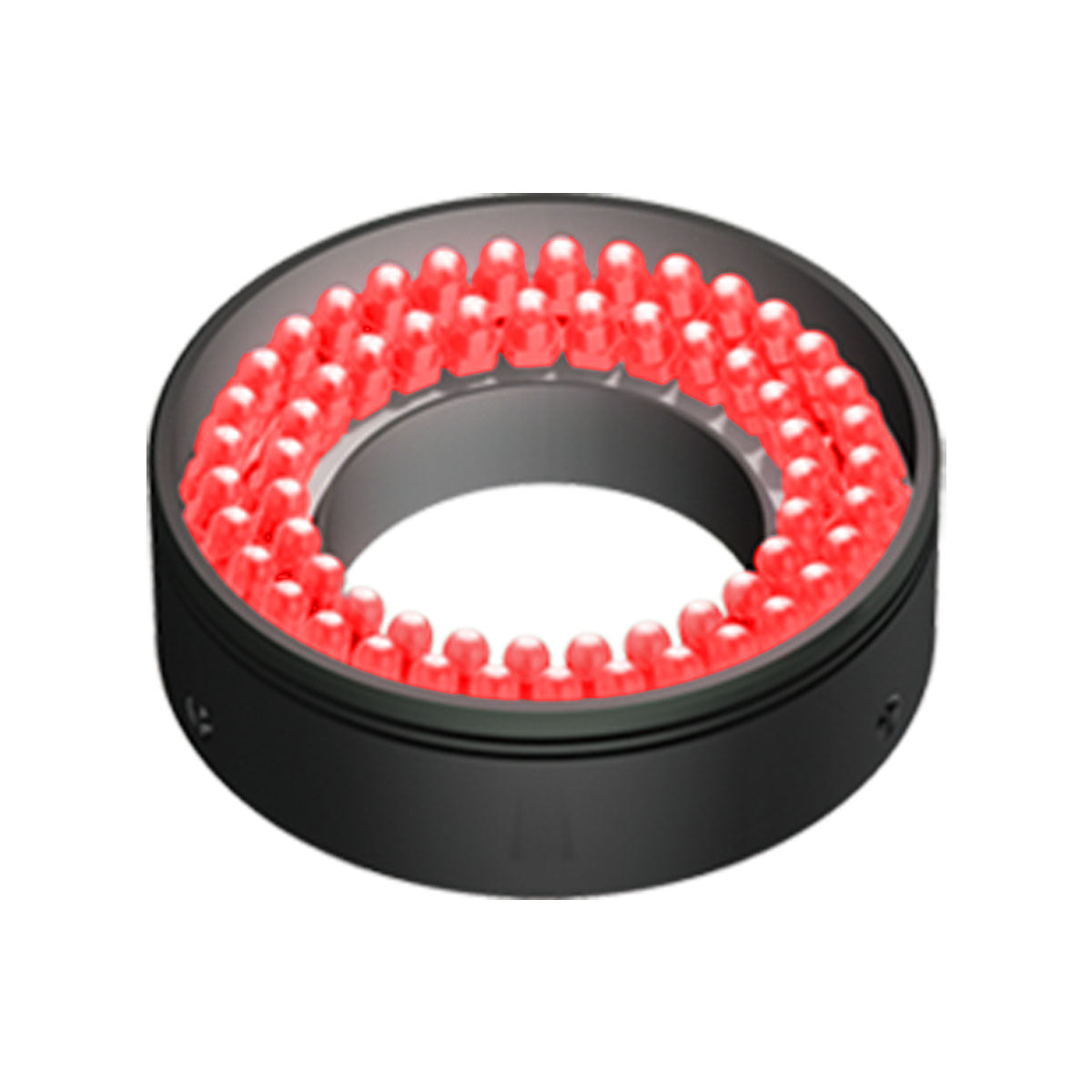
Ring Lights
Uniform frontal illumination for flat surfaces.
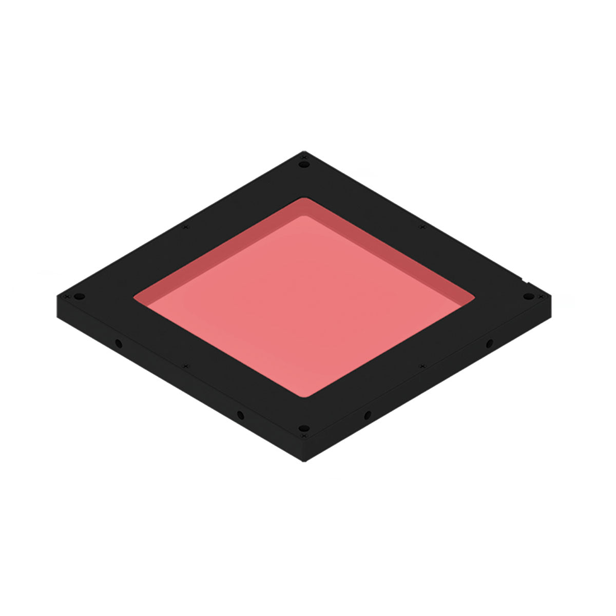
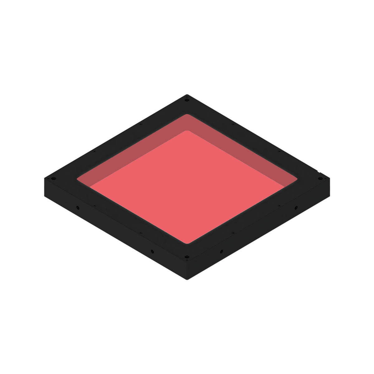
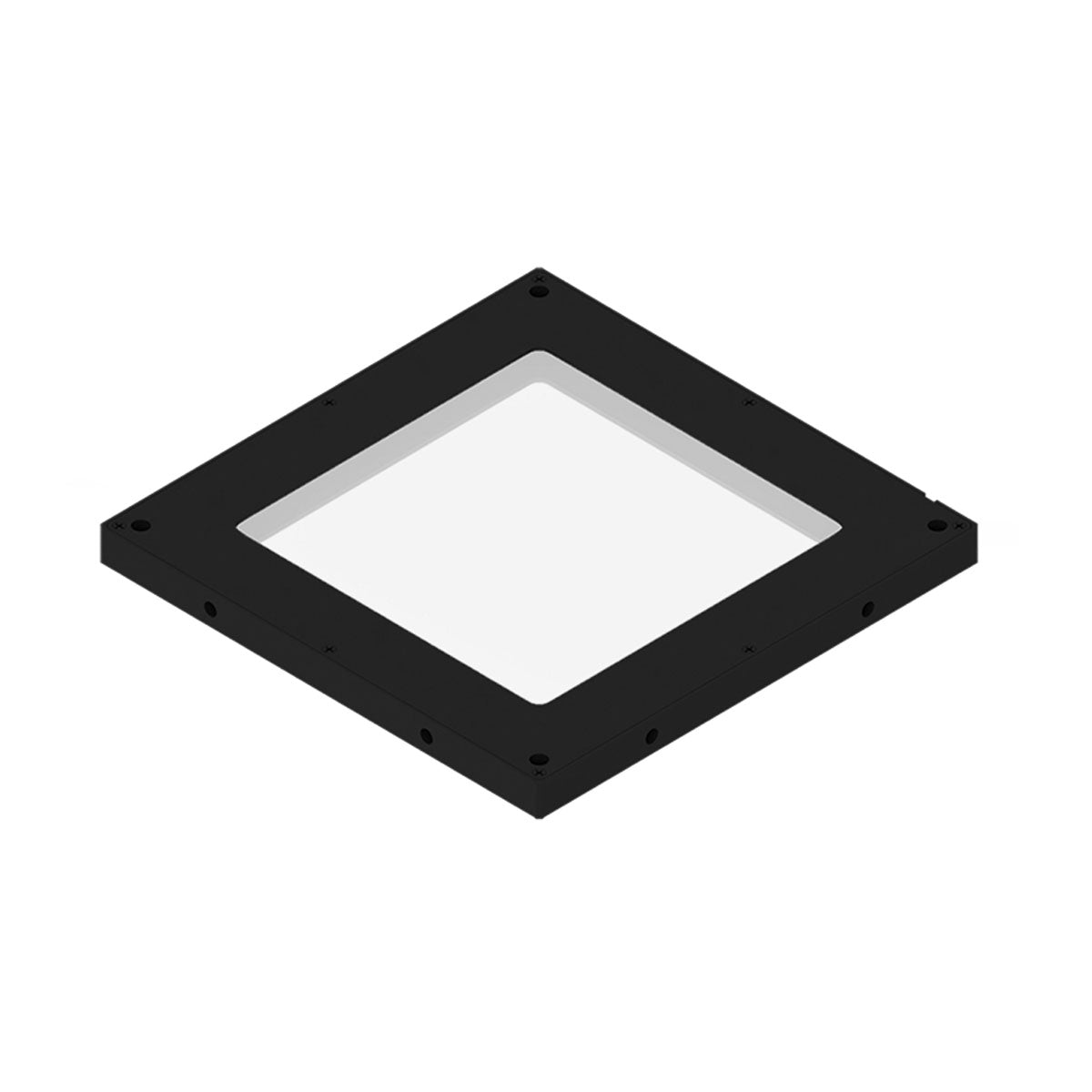
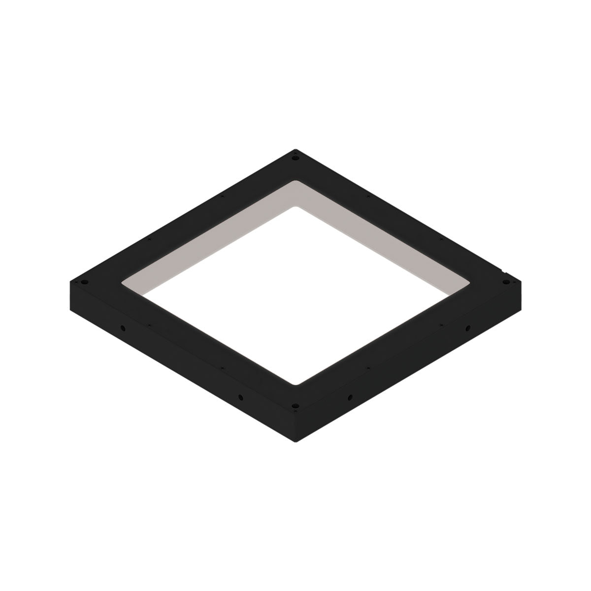
Backlights
Excellent for silhouette measurement and edge detection.
Dome Lights
Diffuse lighting to eliminate glare on reflective surfaces.
Bar Lights
Directional lighting for texture enhancement.
Lighting geometry, angle, wavelength, and intensity all affect inspection results.
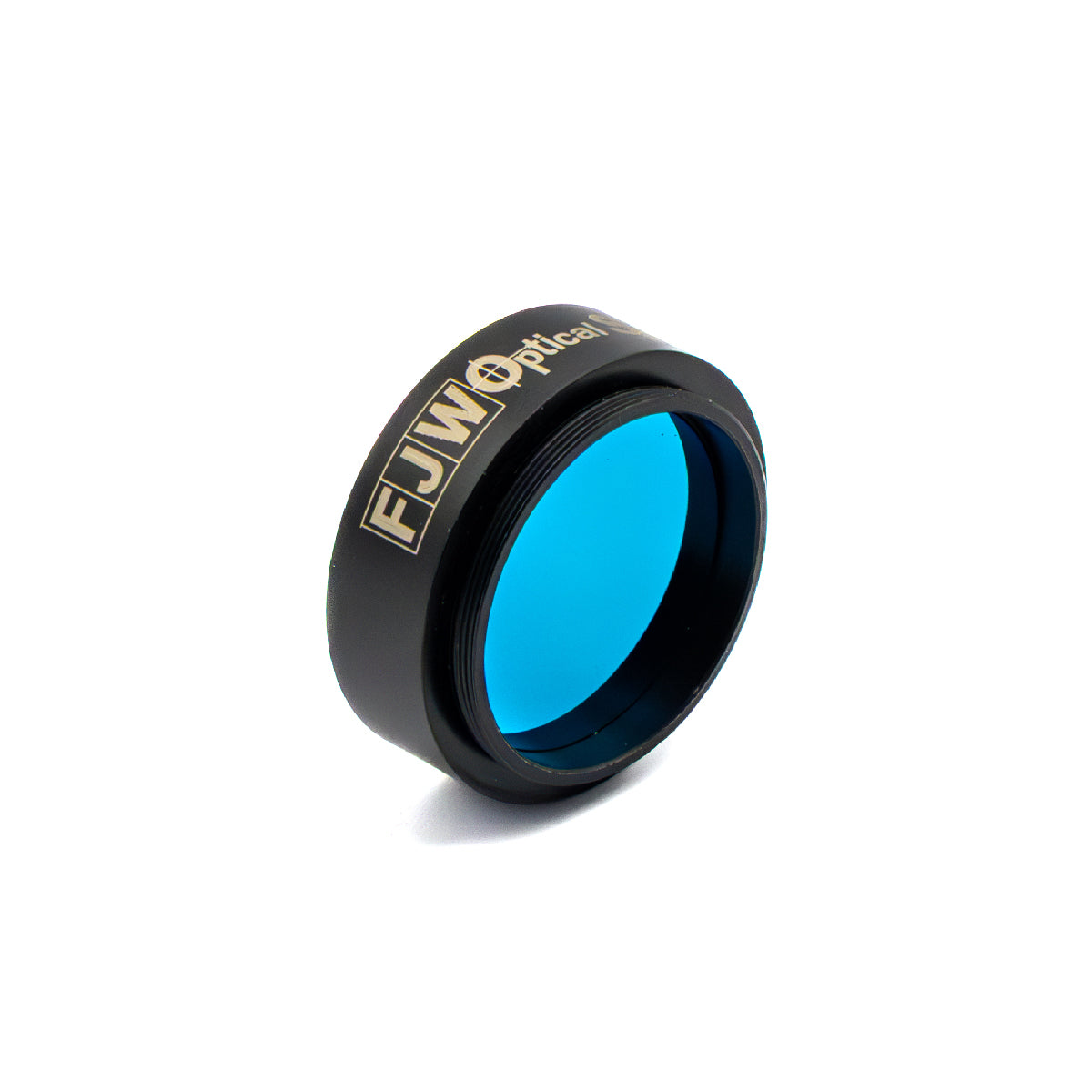
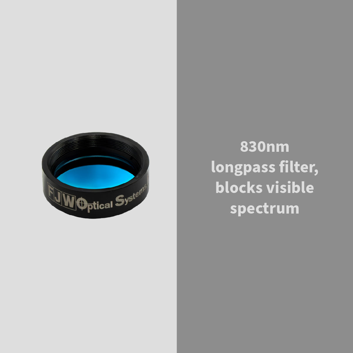
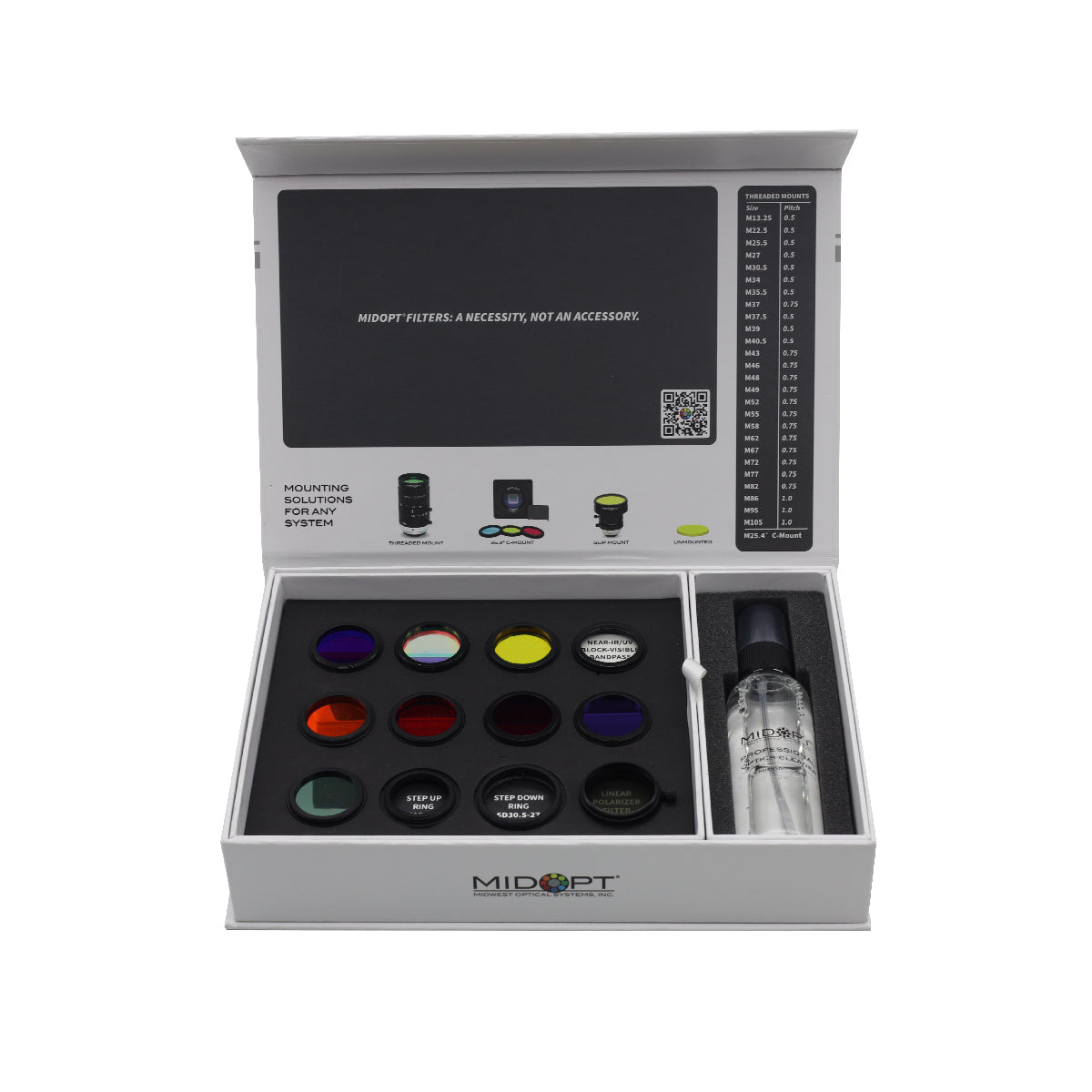
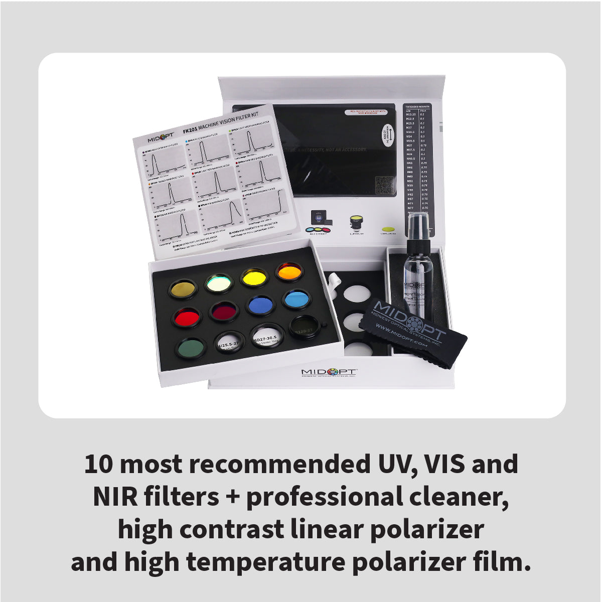
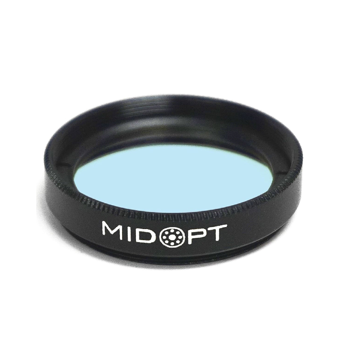
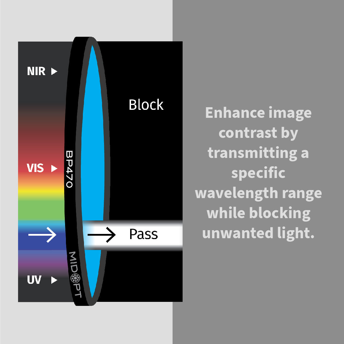
4. Optical Filters
Optical filters refine the light entering the camera sensor.
They are essential when:
- Reducing glare
- Enhancing contrast
- Blocking ambient factory light
- Performing infrared inspection
Common types:
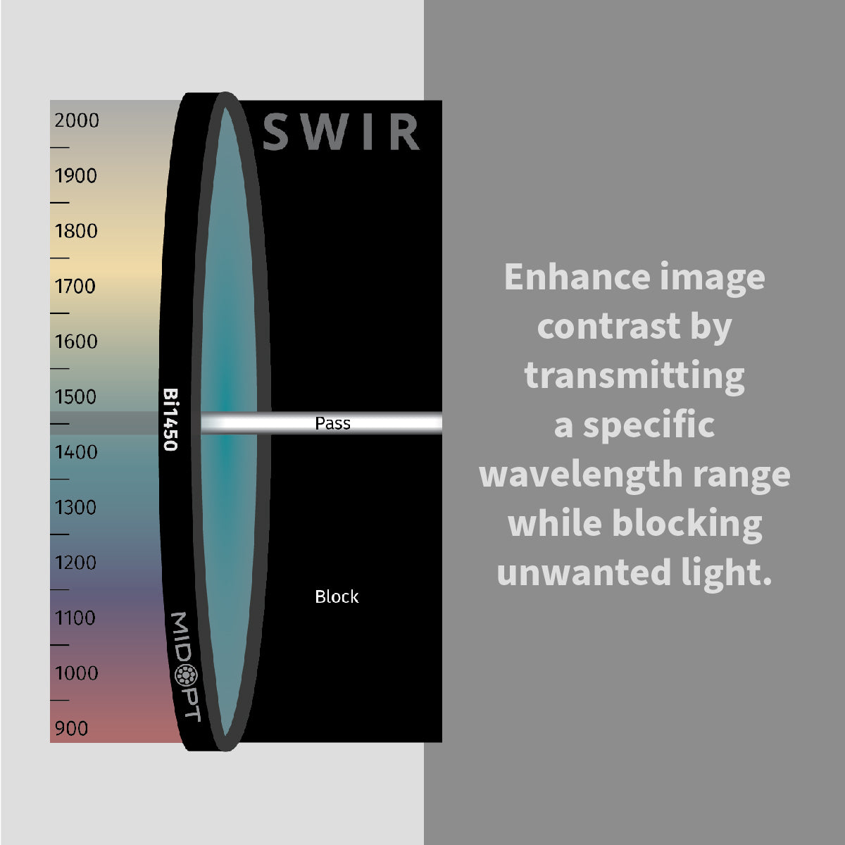
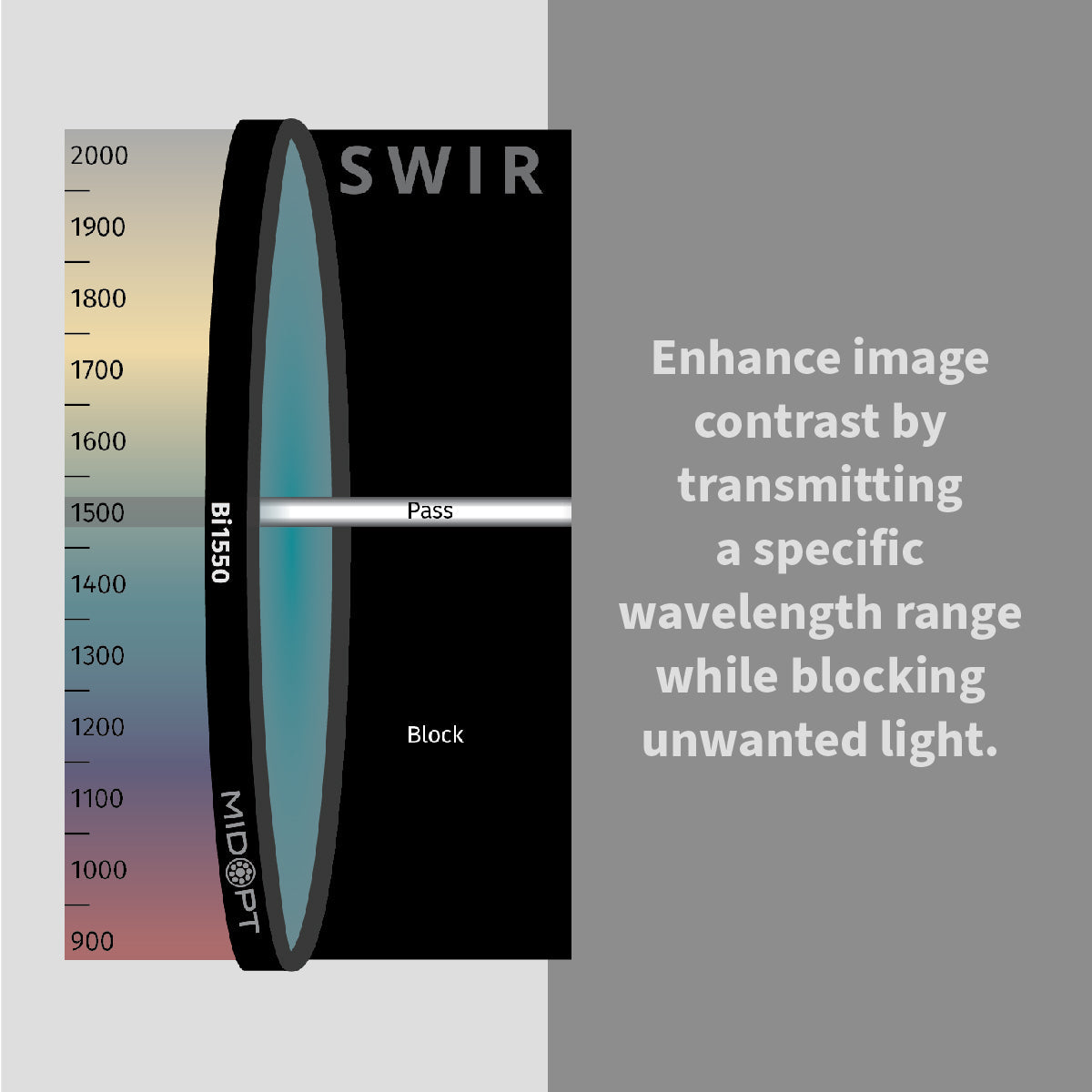
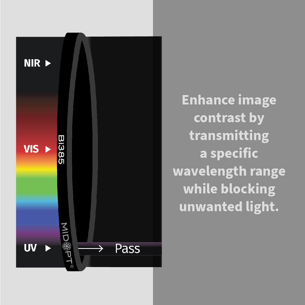
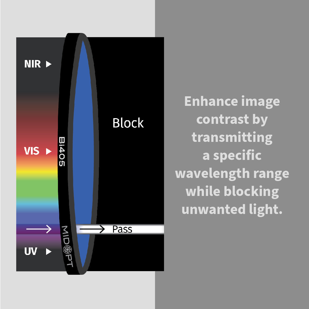
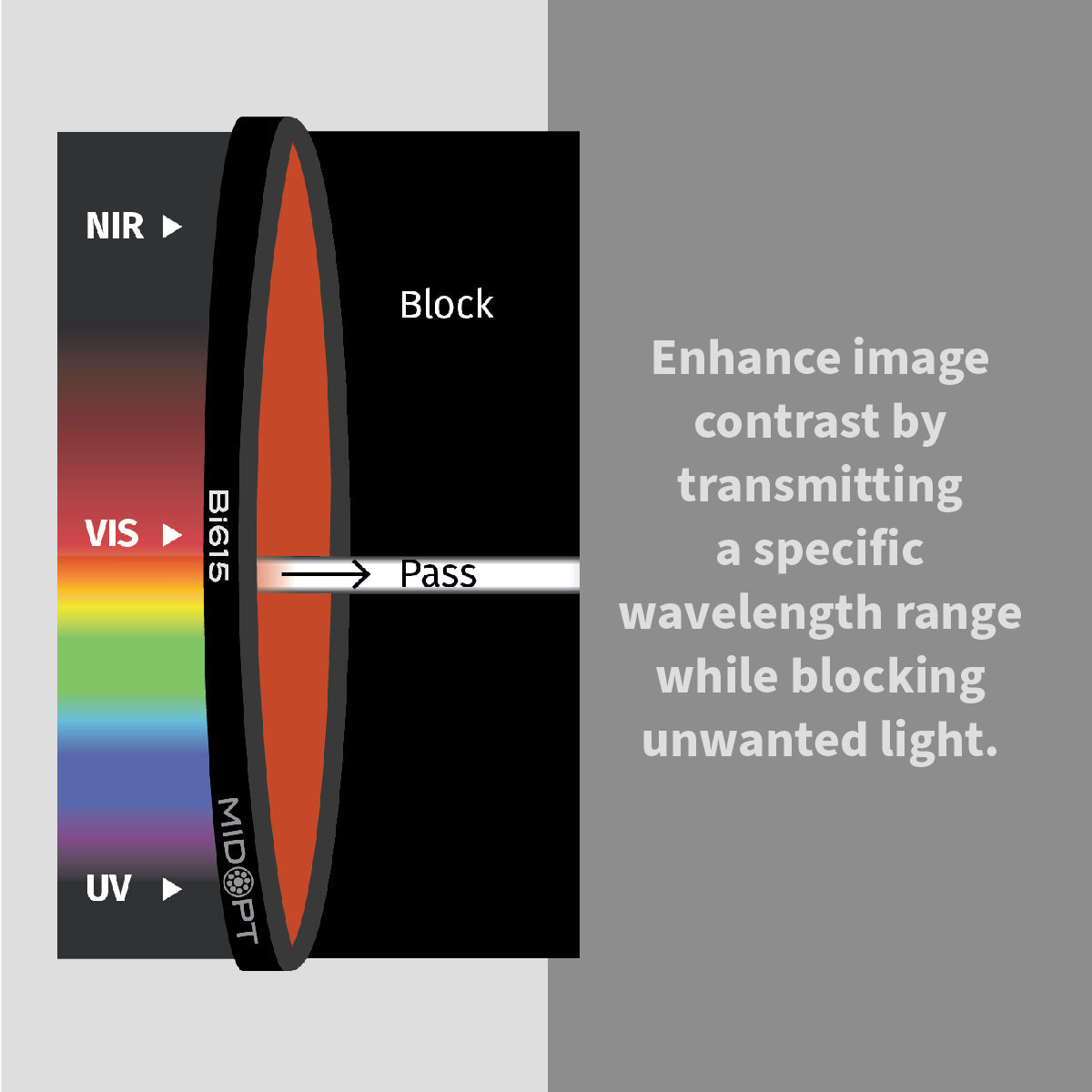
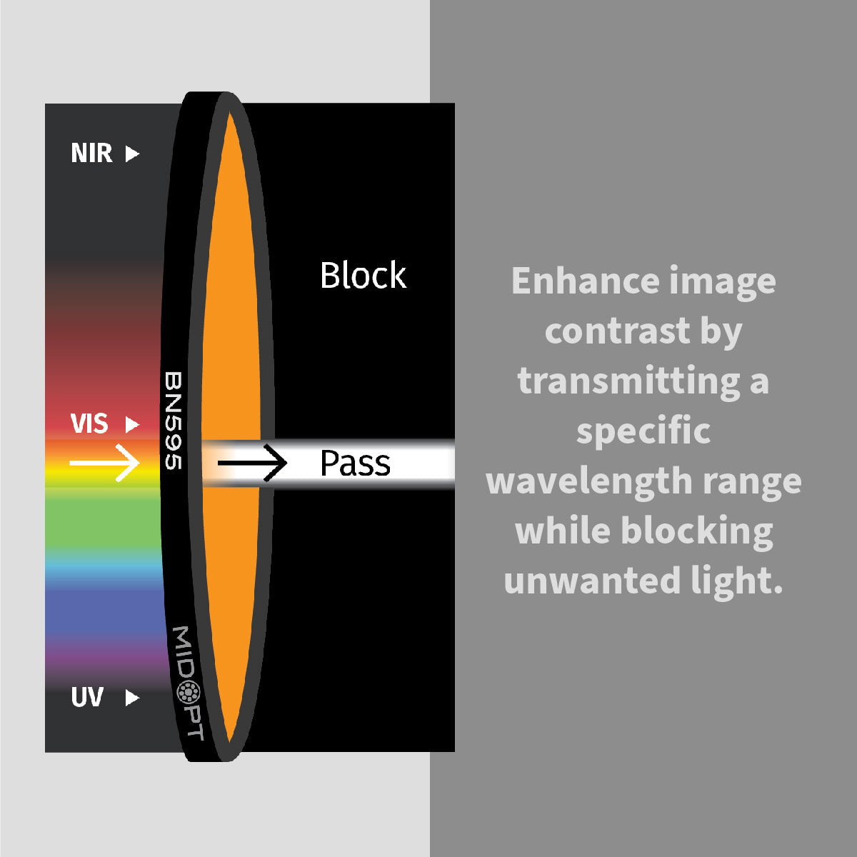
Bandpass Filters
Allow only a specific wavelength to pass.
Polarizing Filters
Reduce reflections from shiny surfaces.
IR Filters
Used in near-infrared inspection systems.
Filters dramatically improve signal-to-noise ratio when properly paired with lighting.
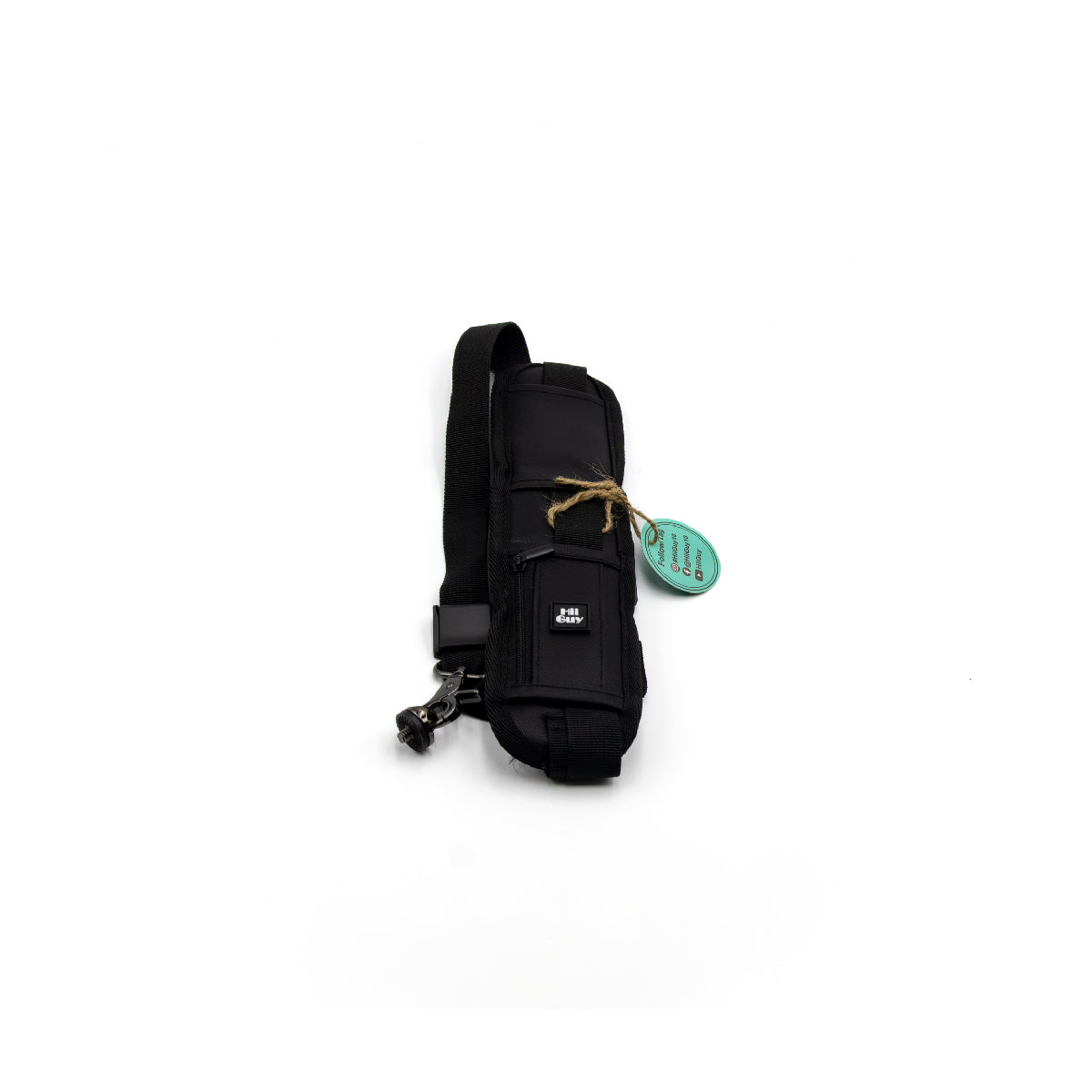
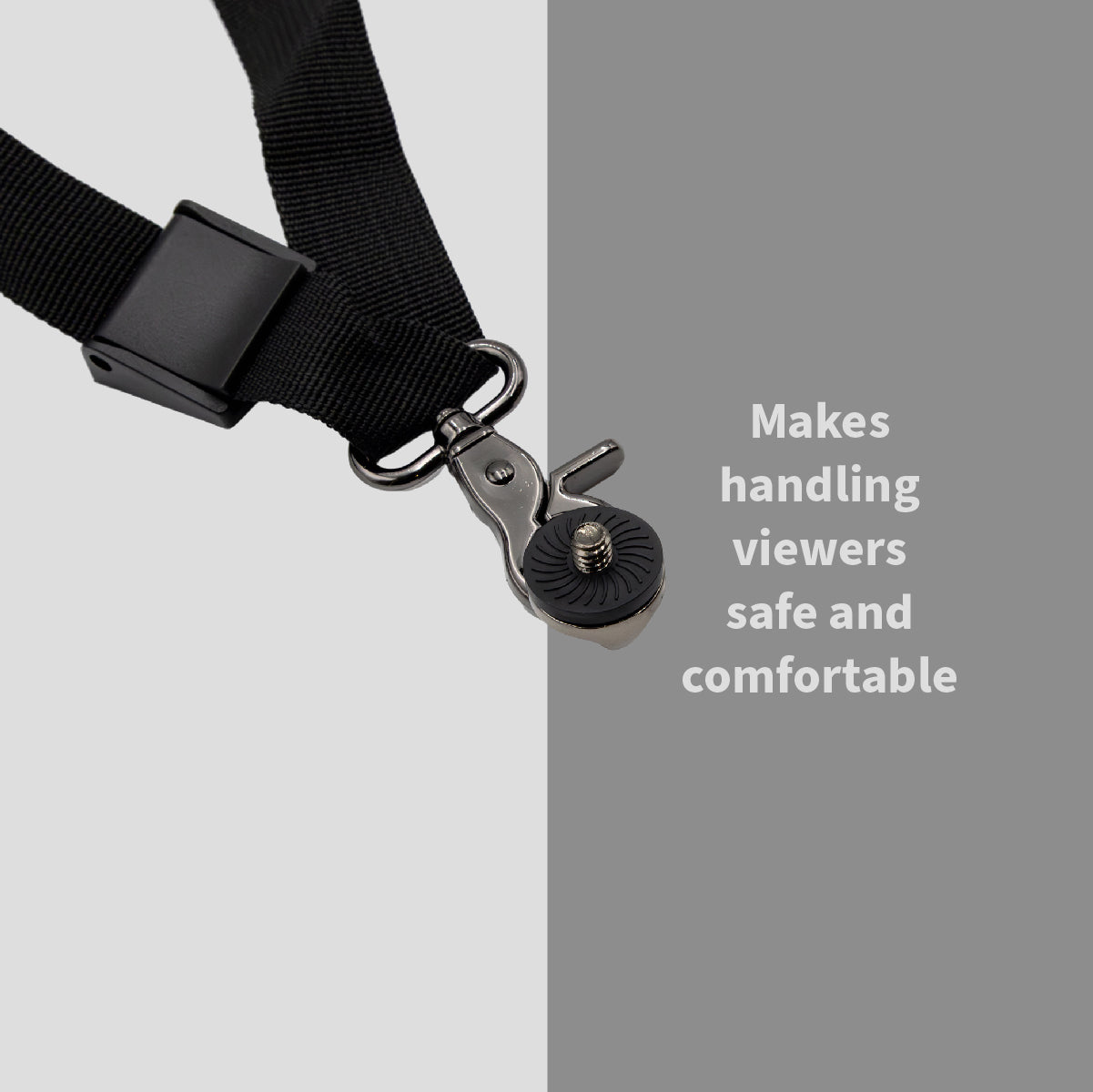
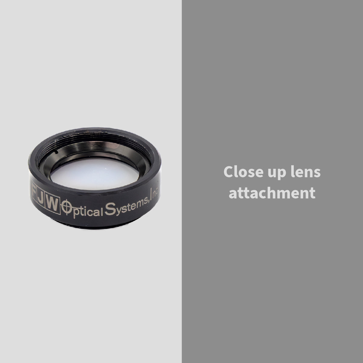
5. Mounting & Mechanical Accessories
Stability is critical.
Vibration or misalignment can destroy measurement accuracy.
Essential accessories include:
- Adjustable mounts
- Extension tubes
- Lens adapters
- Enclosures
- Protective housings
Proper mounting ensures consistent image alignment and repeatability.
Step-by-Step Machine Vision System Design Process
Now let’s combine all components into a structured design approach.
Step 1: Define Inspection Objective
Before choosing hardware, define:
- What defect or feature must be detected?
- What size tolerance is required?
- What speed is the production line?
Without clear objectives, hardware selection becomes inefficient.
Step 2: Calculate Required Resolution
Use this formula:
Minimum Feature Size ÷ Desired Pixel Coverage = Required Pixel Resolution
Example:
If detecting a 0.1 mm defect and needing 4 pixels per feature:
0.1 mm ÷ 4 = 0.025 mm per pixel
This determines camera resolution and lens magnification.
Step 3: Select the Camera
Choose based on:
- Resolution
- Frame rate
- Sensor type
- Interface compatibility
Avoid overspending on resolution you don’t need – processing speed matters.
Step 4: Select the Lens
Match lens to:
- Sensor format
- Working distance
- Field of view
- Distortion tolerance
Test combinations when possible.
Step 5: Design the Lighting Strategy
Lighting should enhance contrast of the feature being inspected.
Examples:
- Scratches → low-angle dark field lighting
- Shape measurement → backlight
- Reflective metal → dome light
Lighting is often the difference between success and failure.
Step 6: Add Optical Filters
Filters improve performance when:
- Ambient light interferes
- High-glare materials are present
- Specific wavelengths enhance feature contrast
For example:
Using a red LED with a matching bandpass filter eliminates most background interference.
Step 7: Mechanical Stabilization
Secure all components using rigid mounting systems.
Ensure:
- No vibration
- Consistent alignment
- Controlled working distance
Common Machine Vision Design Mistakes
Even experienced engineers make these errors:
Choosing Camera First Without Defining Application
Always define inspection goals first.
Ignoring Lighting Design
Lighting affects image quality more than camera specs.
Using Generic Lenses
Industrial lenses are not interchangeable with consumer optics.
Skipping Optical Filters
Filters significantly improve inspection reliability.
Advanced Optimization Strategies (2026)
Modern systems increasingly use:
- High dynamic range (HDR) imaging
- Multi-spectral illumination
- AI-assisted defect detection
- Coaxial lighting setups
- Near-infrared inspection
As inspection tolerances tighten, system optimization becomes critical.
Frequently Asked Questions
How do you design a machine vision system?
Start by defining inspection requirements, then select camera, lens, lighting, filters, and mounting components based on resolution and contrast needs.
What is the most important component in a machine vision system?
Lighting is often the most critical factor because it determines contrast and defect visibility.
How do lighting and filters work together?
Lighting emits specific wavelengths. Filters isolate those wavelengths to reduce noise and improve image clarity.
Can one system handle multiple inspections?
Yes, but it requires careful optical design and possibly multiple lighting configurations.
Machine vision system design is an engineering discipline that requires precise coordination between cameras, lenses, lighting, and optical filters.
When properly designed, a machine vision system delivers:
- Higher inspection accuracy
- Reduced defect escape rates
- Improved production efficiency
- Long-term operational stability
The key is not selecting the most expensive components — but selecting the right ones.